 Virtual Colossus
How do you program a 1960s computer?
Below is an example program sheet for a very “simple” ICT 1301 program, which loops, updating some of the lights on the front of the console and incrementing one of the registers. This page runs through each command, to give an idea of how each one is used.
New to the terms? The glossary explains the IAS, orders, designations, relativisers and the rest.
Programmers used the program sheet to lay out their code, ready for someone to punch onto a pack of cards. First, the programmer would write the program as a flow chart, before writing it on the program sheet.
The top section is for information, including the job being written, the programmer and other useful details. The block number was set if several programmers were each working on different parts of the same routine. It let each programmer refer to their own part of the memory, wherever it was finally placed in the IAS (immediate access store: a fast core store, this computer’s RAM) in the finished program. A senior programmer was given the job of deciding where in memory to put each programmer’s subroutines in the full program.
Each order is made up of four parts: the designation, function, address and relativiser. The column headings are:
- C
- Card number. Each punched card in the “normal” card form holds three order-pairs, each with two functions stored in a single word.
- I
- Instruction number. This lets us jump to a particular instruction later. Each order-pair is made up of 2 commands.
- D
- Designation. A single character or digit, used to enable particular control words.
- F
- Function. A 2-digit decimal value, usually the command function to run.
- A
- Address. Four decimal digits.
- R
- Relativiser. Used to give a relative block to address. The letter B means the current block; a number means another block of code.
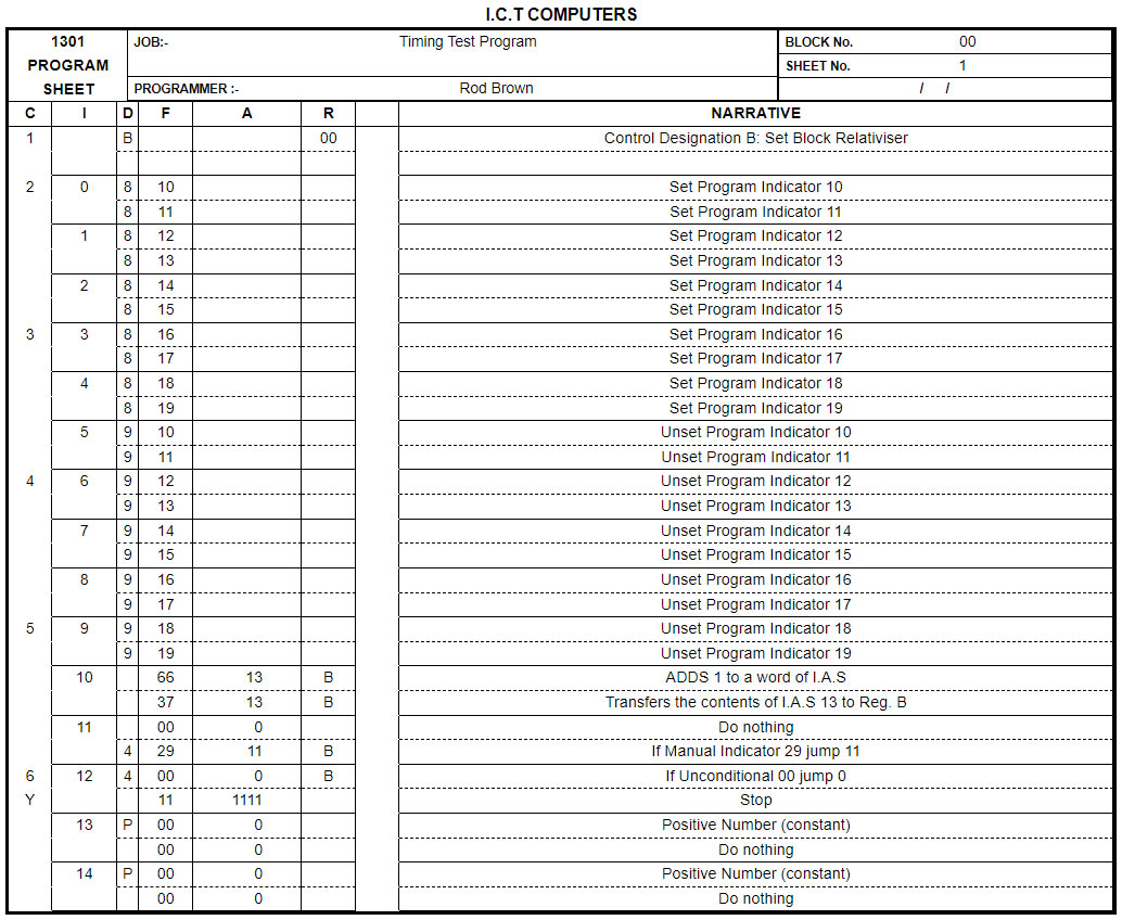
Card 1
| C | I | D | F | A | R | Narrative |
|---|---|---|---|---|---|---|
| 1 | B | 00 | Control designation B: set block relativiser | |||
This first line isn’t a function for the computer’s logic, but a special control word. These are given by a set of single-character commands (for more on these control words, see page 7 of the Initial Orders Manual).
This one is command B, the block relativiser control word. It tells Initial Orders (the bootstrap program) where to store the block of program about to be read: here, at relative position 00 on the drum.
In this case this single command takes up the whole first punched card, as it isn’t actually part of the program.
Card 2
| C | I | D | F | A | R | Narrative |
|---|---|---|---|---|---|---|
| 2 | 0 | 8 | 10 | Set programmed indicator 10 | ||
| 8 | 11 | Set programmed indicator 11 | ||||
| 1 | 8 | 12 | Set programmed indicator 12 | |||
| 8 | 13 | Set programmed indicator 13 | ||||
| 2 | 8 | 14 | Set programmed indicator 14 | |||
| 8 | 15 | Set programmed indicator 15 |
The second punched card (card 2) has three order-pairs, instructions 0, 1 and 2.
The first order has designation 8 and function 10. Together, the designation and function give the operation the computer carries out when it obeys the order.
Designation 8 is a command to set an indicator on the computer. There are three types of indicator, each a Boolean value, either set or unset:
- Automatic indicators: a link between the computer and a program, usually set or unset by the computer, by a peripheral (the printer, card punch and so on) or by a result from the mill (the arithmetic unit). These are numbered 00 to 09.
- Programmed indicators: set, unset and tested by the running program. Think of them as Boolean variables we can switch on and off; they are shown as lights on the console. These are numbered 10 to 19.
- Manual indicators: read-only, set with manual control switches on the console, so the operator can affect the running of a program. These are numbered 20 to 29.
So designation 8 means “set programmed indicator”, and the function says which indicator to set. The first line sets indicator 10 (the first programmed indicator), lighting the first programmed indicator light on the console.
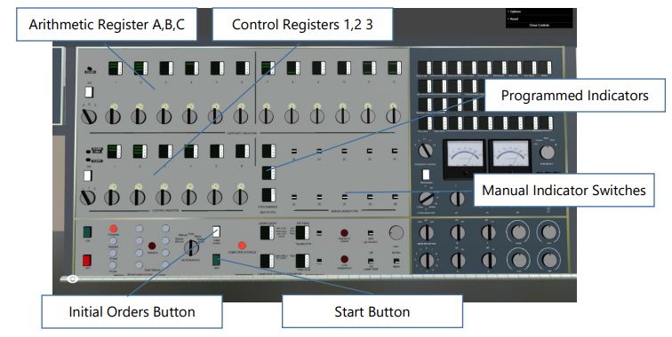
The second order is very similar, setting programmed indicator 11, so the second light on the console comes on. This carries on for the other orders on this card, switching on the first 6 lights on the console.
Card 3
| C | I | D | F | A | R | Narrative |
|---|---|---|---|---|---|---|
| 3 | 3 | 8 | 16 | Set programmed indicator 16 | ||
| 8 | 17 | Set programmed indicator 17 | ||||
| 4 | 8 | 18 | Set programmed indicator 18 | |||
| 8 | 19 | Set programmed indicator 19 | ||||
| 5 | 9 | 10 | Unset programmed indicator 10 | |||
| 9 | 11 | Unset programmed indicator 11 |
Card 3 carries on the pattern for the next two instructions, setting programmed indicators 16, 17, 18 and 19, but instruction 5 is a little different.
The designation for these commands is 9 rather than 8. Designation 9 means unset the programmed indicator given by the function value.
So we start unsetting indicators 10 and 11, putting out those lights on the console. You can probably guess what the next card will be!
Cards 4 and 5
| C | I | D | F | A | R | Narrative |
|---|---|---|---|---|---|---|
| 4 | 6 | 9 | 12 | Unset programmed indicator 12 | ||
| 9 | 13 | Unset programmed indicator 13 | ||||
| 7 | 9 | 14 | Unset programmed indicator 14 | |||
| 9 | 15 | Unset programmed indicator 15 | ||||
| 8 | 9 | 16 | Unset programmed indicator 16 | |||
| 9 | 17 | Unset programmed indicator 17 | ||||
| 5 | 9 | 9 | 18 | Unset programmed indicator 18 | ||
| 9 | 19 | Unset programmed indicator 19 |
Card 4 and the first order-pair of card 5 carry on as the last card, unsetting each of the programmed indicator lights in turn.
| C | I | D | F | A | R | Narrative |
|---|---|---|---|---|---|---|
| 10 | 66 | 13 | B | Add 1 to a word of IAS | ||
| 37 | 13 | B | Transfer the contents of IAS 13 to register B |
From instruction 10, we start to meet some new functions. There is no designation, so we can look straight at the function to see what the command does. The first order is function 66, “add 1 to a word of IAS”: increment the number at the given memory address by 1. The basic address given is 0013, and the relativiser tells the computer which block of memory it is in: here, the letter B, meaning the current block.
To understand the relativiser, imagine the senior programmer has decided to store the whole program block at IAS address 0200. Then, when we ask to increment address 0013, the computer knows we mean address 0213. If the block is used somewhere else, say at address 0600, we don’t need to rewrite all our addresses: they adjust automatically to the new position, 0613.
The second order of instruction 10 is function 37, “transfer the contents of the given IAS address to register B”. Again, the address is this block’s 0013, so it transfers the value we’ve just incremented into register B, overwriting its current value.
You may be asking what exactly is at block address 0013. Let’s jump ahead and take a quick look at the next card, and address 0013.
| C | I | D | F | A | R | Narrative |
|---|---|---|---|---|---|---|
| 13 | P | 00 | 0000 | A positive number | ||
| 00 | 0000 |
At instruction 13 we find another of the special command designation letters, this time P. P tells Initial Orders that we are defining a positive value. The ICT 1301’s word is 12 digits, so we set the 12 digits of the value in the function and address of the two orders. Here we are setting address 13 to a positive value of zero.
Looking back at the order-pair in instruction 10, you can see that we increment this zero value by 1 and transfer the result into register B.
| C | I | D | F | A | R | Narrative |
|---|---|---|---|---|---|---|
| 11 | 00 | 0 | Do nothing | |||
| 4 | 29 | 11 | B | If manual indicator 29, jump to 11 |
The first order of instruction 11 is function 00, which is “do nothing”! Ignoring that for the moment, the second order of the pair introduces yet another designation: 4.
Designation 4 means: check one of the indicators (automatic, programmed or manual) and, if it is set, jump to the program address given. If it is not set, the program carries on to the next instruction.
So what is indicator 29, which this checks? From the list of indicators above, indicator 29 is one of the ten manual switches on the console.
So this instruction says: “Check switch 29 on the console. If it is set, jump to program address 0011 (in this block).” Instruction 0011 is this very instruction, so this is a pause loop: if the operator sets switch 29 on, the program pauses, and when the switch is unset, it carries on.
Card 6
| C | I | D | F | A | R | Narrative |
|---|---|---|---|---|---|---|
| 6 (Y) | 12 | 4 | 00 | 0 | B | If unconditional 00, jump to 0 |
| 11 | 1111 | Stop | ||||
| 13 | P | 00 | 0000 | Positive number (constant) | ||
| 00 | 0000 | |||||
| 14 | P | 00 | 0000 | Positive number (constant) | ||
| 00 | 0000 |
Instruction 12, the first order-pair of card 6, again has designation 4 (check an indicator and jump to a new address if it is set).
The indicator checked here is 00, one of the special automatic indicators set by the computer. Indicator 00 is a special one that is always set.
So this instruction always jumps to the given address: here, this block’s address 0000, the start of the program.
There is another instruction written for the second order of the pair: function 11, a command to stop the program and show the error number 0000 on the console. Why 0000, and not 1111 as the address on the card says? Control register 1 is incremented before the CPU stops, so the value shown in control register 3 is one more than the address field. In this program the stop command should never run, as the command before it jumps to address 0, but I suspect it is there as a safety measure, to make sure the program can’t run on into unspecified addresses if something goes very wrong and, somehow, indicator 00 fails!
The last two instructions, 13 and 14, we’ve already discussed: they just set two words to zero so we can use them later (the number stored at instruction 14 isn’t used in this program at the moment).
You may have spotted one other difference on this card: the Y written just under the card 6 reference on the sheet. This is a note for the person punching the card, to punch a special marker on it showing that this is the end of the block. An X here normally marks the end of a block, a Y the end of a library subroutine, and a Z normally the last card of the program.
What does the program do?
First it sets all 10 programmed indicator lights one after another, then switches them all off again in order. Next it increments a counter and puts it in register B (we can show register B on the console, and watch the counter count up from 1 continuously). Finally, if you set manual switch 29 on the console, the program pauses, and carries on when you set the switch off again.
This program was used on the real Flossie when it was running, and we know exactly how long it took to run several loops. So we have also been able to use it to check that this simulation runs the commands at the same speed as the original computer. You can find out how to run it on Virtual ICT 1301 on the using the simulation page.
Hopefully this has given you an idea of how to write a program for the ICT 1301. More examples, and a list of all the functions available, are in the manuals below. Do let me know if you write any new programs for this computer!
The manuals
These manuals were scanned to PDF by the ICT 1301 Resurrection Project.
Initial Orders Manual
Programmers Reference Manual
- Header and contents
- Part 1: Introduction
- Part 2: The Central Processor (part a)
- Part 2: The Central Processor (part b)
- Part 3: Peripheral Equipment (part a)
- Part 3: Peripheral Equipment (part b)
- Part 3: Peripheral Equipment (part c)
- Part 4: Programming Techniques (part a)
- Part 4: Programming Techniques (part b)
- Part 5: Software Facilities
- Part 6: Reference Tables and Glossary
Operators Reference Manual
For more information in the meantime, see the ICT 1301 Resurrection Project.